

How To Repair Fabric Aircraft
Suggested Citation:"7 Aircraft Maintenance and Repair." National Enquiry Quango. 1996. New Materials for Adjacent-Generation Commercial Transports. Washington, DC: The National Academies Press. doi: 10.17226/5070.
×
4
Aircraft Operations
Consideration of aircraft operations, including inspection, maintenance, and repair procedures is crucial in the development and awarding of new materials and structures. This part of the commission's report focuses on the functioning and monitoring of materials and structures in a service surroundings.
This office is organized in two chapters:
-
Affiliate 7, "Shipping Maintenance and Repair," describes the issues related to maintenance of commercial ship aircraft. The lessons learned from the aging of metal and blended structure are discussed.
-
Chapter 8, "Nondestructive Evaluation," describes current aircraft inspection practices and identifies needs for improved nondestructive evaluation techniques and promising technologies for the future.
Suggested Citation:"7 Aircraft Maintenance and Repair." National Enquiry Council. 1996. New Materials for Side by side-Generation Commercial Transports. Washington, DC: The National Academies Press. doi: x.17226/5070.
×
This page in the original is blank.
Suggested Citation:"7 Aircraft Maintenance and Repair." National Research Council. 1996. New Materials for Next-Generation Commercial Transports. Washington, DC: The National Academies Printing. doi: 10.17226/5070.
×
vii
Aircraft Maintenance and Repair
The successful utilization of new materials and structural concepts relies on maintenance programs that cost-effectively ensure passenger safety. This chapter is an overview of the current feel in aircraft maintenance programs, including inspection and repair processes, lessons learned from aging shipping, and futurity needs to back up new materials and structural concepts.
AIRLINE MAINTENANCE
Maintenance programs are evolved and adult for each new type of aircraft based on previous experience with similar materials, engines, components, or structures. New materials or structures, for which experience is express, are observed more often until a basic level of confidence is established. Time extensions to inspection intervals are based on observations made during routine service checks. A typical airline maintenance and service plan is outlined in table vii-ane. The objectives of an effective maintenance program are every bit follows (Edwards, 1994):
-
Ensure, through maintenance action, that the inherent safety and reliability imparted to an shipping by its pattern are sustained.
-
Provide opportunities to restore levels of safe and reliability when deterioration occurs.
-
Obtain information for design modification when inherent reliability is non adequate.
-
Achieve the above at the lowest possible cost.
Structural Maintenance
Any new aircraft programme is based on assessing structural design information, fatigue and harm tolerance evaluations, service experience with similar aircraft structures, and pertinent test results. More often than not, the maintenance task evaluates sources of structural deterioration including adventitious damage, environmental deterioration, and fatigue damage; susceptibility of the construction to each source of deterioration; the consequences of structural deterioration to standing airworthiness including effect on shipping (e.g., loss of function and reduction of residual strength, multiple-site or multiple-element fatigue damage, the effect on aircraft flight or response characteristics caused by the interaction of structural damage or failure with systems or power constitute items, or in-flight loss of structural items); and the applicability and effectiveness of various methods of detecting structural deterioration, taking into business relationship inspection thresholds and repeat intervals.
Component Maintenance
The awarding of new materials will not cause undue maintenance difficulties or hardship for the airlines provided the shipping designer is familiar with component experience. Airline experience indicates that hardware items article of clothing out, merely statistical former-age wearable-out in complex mechanical, electrical, and avionic components is not a dominant pattern of failure. In fact, over 90 percent of generic part types show either random distribution of failure or gradually increasing probability of failure with age (Edwards, 1994).
The reliability of a part or component of aircraft hardware is but as expert as its inherent design (supported by acceptable maintenance) allows information technology to exist. Hence, information technology is generally accustomed that (one) good maintenance allows parts to reach their potential reliability; (two) overmaintaining does not better reliability, merely does waste coin; and (three) undermaintaining tin degrade reliability. In general, key design changes are required to correct inherent component reliability bug.
There are three approaches to preventative maintenance that accept proven to be constructive. The first method, hard time, involves removing a unit from service when it reaches a pre-ordained parameter value. The second method, functional check or inspection, involves monitoring a characteristic dimension or usage/operating parameter of a piece of hardware to determine if it is still suitable for continued performance, or if it should be removed to prevent an in-service failure. The third method, functional verification, requires performing an operational check of hardware role(south) to determine each function's availability if it is normally hidden from the scrutiny of the flight and operating coiffure.
There are many components for which measurement of deterioration, periodic removal for maintenance, and subconscious function verification are not economically feasible or beneficial. Such parts require routine performance or reliability
Suggested Citation:"7 Aircraft Maintenance and Repair." National Enquiry Council. 1996. New Materials for Next-Generation Commercial Transports. Washington, DC: The National Academies Press. doi: ten.17226/5070.
×
Tabular array vii-1 Typical Airline Maintenance and Service Plan
| When Service is Performed | Type of Service Performed | Impact on Airline Service |
| Prior to each flight | ''Walk-effectually"—visual check of aircraft exterior and engines for impairment, leakage, and brake and tire wear | None |
| Every 45 hours (domestic) or 65 hours (international) flight fourth dimension | Specific checks on engine oils, hydraulics, oxygen, and specified unique aircraft requirements | Overnight layover service |
| Every 200–450 hours (22–37 days) flying time | "A" check—detailed check of shipping and engine interior, services and lubrication of systems such as ignition, generators, cabin, air conditioning, hydraulics, structure, and landing gear | Overnight layover service |
| Every 400–900 hours (45–75 days) flying fourth dimension | "B" bank check (or "L" check)—torque tests, internal checks, and flying controls | Overnight layover service |
| Every 13–15 months | "C" check—detailed inspection and repair program on aircraft engines and systems | Out of service for 3–5 days |
| Every ii years (narrow-torso aircraft) | Inspection and reapplication of corrosion protective coatings | Out of service up to xxx days |
| Every 3–5 years | Major structural inspections with attention to fatigue impairment, corrosion, etc. Aircraft is dismantled, repaired, and rebuilt. Aircraft is repainted every bit needed | Out of service upwardly to 30 days |
monitoring, and no preventive maintenance is required or desirable. Modern shipping are more tolerant of failures than older aircraft designs because of the increased redundancy provided in the blueprint.
Generally, almost airlines classify specific component maintenance tasks as follows:
-
lubrication or servicing, where the replenishment of the consumable reduces the charge per unit of functional deterioration;
-
operational or visual cheque, where identification of the failure must exist possible;
-
inspection or function check, where reduced resistance to failure must be detectable and the rate of reduction in failure resistance must exist predictable;
-
restoration, where the item must bear witness functional deposition characteristics at an identifiable age, have a big proportion of units survive to that historic period, and be able to exist restored to a specific standard of failure resistance; and
-
discard, where the detail must show functional deposition characteristics at an identifiable age, and a big proportion of units are expected to survive to that age.
Malfunctions of components should be evident to the operating crew, accept no direct adverse effect on safety (whether they occur as a single or multiple upshot), and minimize the consequence on the operation of the aircraft itself.
SERVICE EXPERIENCE
Effective application of new materials on commercial aircraft requires the designer to consider potential sources of damage or degradation in operating environments and to develop a maintenance and repair approach to address them. Impairment may occur due to flight loads, thermal and environmental cycles, and shipping performance and servicing activities. A number of valuable lessons take been learned from
Suggested Citation:"7 Aircraft Maintenance and Repair." National Research Council. 1996. New Materials for Adjacent-Generation Commercial Transports. Washington, DC: The National Academies Printing. doi: 10.17226/5070.
×
previous feel with metal and composite structure in the current fleet. These lessons provide evaluation criteria in the application and servicing of new materials and structures.
Ramp and Maintenance Damage
An International Air Transport Clan survey estimates that 36–40 percentage of harm to shipping is from ramp and maintenance impairment, sometimes called friendly foreign object impairment (IATA, 1991). Figure 7-1 shows a diagram of the Boeing 777 shipping interfaces with servicing and other equipment (Boeing, 1994b). These areas are peculiarly prone to harm and require robust material performance in these locations.
To make up one's mind the extent of groundhandling impairment, 11 airline operators were queried for footing harm history during the years 1990 to 1993 (Boeing, 1994a). Of the 2,241 incidents reported, more than a third were from unknown causes. A tabulation of the causes of damage is given in table 7-2.
Ramp and maintenance damage tin represent significant costs to the airlines. The repair of a damaged component is only part of the price. The airline as well bears the cost of flying delay or cancellation and the effects on connections and aircraft rotations.
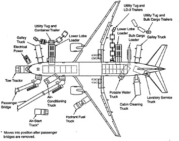
FIGURE 7-1 Diagram of aircraft interfaces with servicing and other equipment.
Source: Boeing (1994b).
TABLE 7-2 Causes of Ground Damage to Aircraft
| Cause of Failure | Number of Incidences |
| Unknown | 773 |
| Catering | 137 |
| Belt loader | 122 |
| Loader | 101 |
| Lavatory and water service | 66 |
| Container | 44 |
| Jetway | 246 |
| Baggage cart | 127 |
| Tug/towbar/taxi | 109 |
| Maintenance | 86 |
| Cargo loading | 50 |
| Fueling | 33 |
| SOURCE: Boeing (1994a). | |
Crumbling Aircraft
In April 1988, an Aloha Airlines Boeing 737-200 experienced an in-flight structural failure in which a large section of the upper fuselage ripped open and separated from the aircraft. The failure resulted from multiple-site damage (MSD) and corrosion. In this instance, MSD was the link-upwards of
Suggested Citation:"vii Aircraft Maintenance and Repair." National Research Council. 1996. New Materials for Side by side-Generation Commercial Transports. Washington, DC: The National Academies Printing. doi: 10.17226/5070.
×
modest fatigue cracks extending from adjacent rivet holes in a longitudinal lap joint in the fuselage. The accident focused international attention on the bug of operating an crumbling commercial armada.
In 1990 approximately 46 percent of the U.S. commercial air transport armada was over 15 years old, and 26 percent was over xx years former. If current usage and replacement trends continue, the number of aircraft over 20 years one-time will double past the year 2000. Currently some 3,200 aircraft are afflicted past FAA Airworthiness Directives that business concern operation and maintenance of the aging fleet. The review of feel with aging shipping has caused an increase in the accent on stress corrosion, corrosion, fatigue, and MSD bug. This feel has caused, in turn, the selection of new shipping alloys with meliorate constituent chemistry control or changes in heat treatment tempers. Also, information technology has stimulated the development of new organic finishes that significantly retard corrosion, besides as the implementation of blueprint practices to vastly improve corrosion resistance.
The FAA and NASA developed a cooperative research attempt aimed at providing a technological ground for ensuring the connected safe operation of the crumbling commercial aircraft fleet. Each agency adult a programme consequent with its mission. The FAA's National Crumbling Aircraft Research Program addresses the aging shipping structural safe concerns and provides certification authorities and operators with the tools to see those concerns. NASA's Airframe Structural Integrity Program is focused on developing advanced integrated technologies to economically audit for damage and to analytically predict the residual strength of older airplanes. Together these programs form the technological basis for a cooperative effort with U.Due south. industry to accost the critical aging shipping issues.
Multiple-Site Impairment
MSD is a course of widespread fatigue damage that is characterized by small cracks emanating from structural details such every bit fastener holes (Sampath, 1993). If cracks emanate from adjacent fastener holes, they have the potential to link up and pb to unexpected catastrophic failures every bit described in the previous section. Besides, even without link-upward, multiple-site cracks can severely degrade the adequacy of the structure to withstand major harm from other detached sources equally is described afterward in this section.
In the past, the standard industry practice was to visually inspect the airframe for damage. Various levels of inspections ranging from daily walk-around inspections to detailed tear-downwardly inspections were performed. Instrumented nondestructive evaluation (NDE) methods such as eddy current probes were used only to audit local regions of the construction where previous cracking bug had occurred. While these inspection methods were labor intensive and highly subjective, they were acceptable because the airframe was designed to survive a two-bay pare crack with a severed frame or stiffener. This design criterion was established to enable the airplane to tolerate major detached source damage (i.e., such as might exist encountered as a event of an engine structural failure) as well as large cracks resulting from the link up of smaller fatigue cracks or the unstable propagation of manufacturing flaws or other service-induced impairment. Such damage is big enough that it should be easily detected, and the operator does not need to search for small cracks to ensure the structural integrity of the airframe. All the same, this "fail-prophylactic" philosophy assumed that the structure adjacent to the major damage (e.g., the two-bay fissure) was free of MSD. Design balance forcefulness requirements were based on this assumption. However, the existence of very small cracks (e.thou., a few hundredths of an inch or tenths of a millimeter in length) in the next construction can severely degrade this residual strength and thus jeopardize the safety of the aeroplane as information technology did in the Aloha Airlines incident. Therefore, inspection of crumbling aircraft has become much more onerous than for newer aircraft because safe is vitally dependent on the detection of the very small cracks associated with this onset of MSD. This represents a major claiming to the inspection and aircraft industries.
The principal technical needs are (1) to develop and verify advanced NDE engineering that tin reliably and economically notice disbonds, small MSD fatigue cracks, and corrosion and characterize their consequence on the remainder forcefulness; and (ii) to develop and verify advanced fracture mechanics and structural analysis methodology to predict fatigue crack growth and residual strength of airframe structures to determine in-service inspection thresholds and repeat intervals, quantitatively evaluate inspection findings, and design and certify structural repairs. NDE methods related to MSD are described in chapter viii, and fracture mechanics and structural assay methods are described in chapter 6.
Corrosion
Corrosion of aging aircraft has been described as an insidious problem (Marceau, 1989). While other aging mechanisms, such as habiliment and fatigue, are somewhat predictable and tin be addressed by the airline maintenance programs to preclude major structural problems, corrosion—especially in its localized forms—is very difficult to predict and discover. Factors that influence the extent of corrosion on aircraft are materials selection, blueprint, component processing and finishing, operational environments, and maintenance programs.
Information technology is anticipated that airplanes manufactured today will experience fewer corrosion problems than those in the electric current aged armada considering of meaning blueprint and corrosion protection improvements that have been implemented and because of operators' increased awareness of the role of these improvements in preventive maintenance. Clearly, maintenance
Suggested Citation:"7 Aircraft Maintenance and Repair." National Research Council. 1996. New Materials for Next-Generation Commercial Transports. Washington, DC: The National Academies Press. doi: 10.17226/5070.
×
and corrosion control programs will continue to play a major part in the command of corrosion equally airplanes age.
Some examples of design improvements to reduce corrosion on the Boeing 777 (Marceau, 1994) include:
-
enhanced drainage, especially in the keel of the aircraft;
-
the sealing of faying surfaces in corrosion-prone areas;
-
the application of improved terminate systems;
-
liberal use of corrosion-preventive compounds;
-
implementation of a practiced corrosion control maintenance program; and
-
improved admission for inspection of corrosion-prone areas.
Major airline fleets include aircraft ranging in age from new to 25 years old. Consequently, the degree of corrosion protection incorporated into the airplane varies from limited protection for older aircraft to fairly extensive protection for newer shipping. Corrosion control programs are tailored to private fleets, depending on age, prior experience, flight surroundings and degrees of corrosion protection incorporated prior to the delivery of the aircraft (DeRosa, 1995). All protective finishes are maintained and corrosion prevention compounds are applied during periodic maintenance. Critical areas that are prone to excessive corrosion include areas below the galleys, doorways, lavatories, cargo compartment subfloors, within external fairings, and the bilges which are all treated at iv-year intervals. Landing gear wheel wells and wing spars are treated yearly. Longer intervals of time are allowed betwixt reapplications of corrosion prevention compounds in the case of less-severe environments.
Aging aircraft repairs have typically involved upper-peel lap fastener replacement, nonbonded pare panel replacement, pare lap doubler repairs, frame reinforcement, entryway door and scuff-plate doublers, replacement bushings and clevis joints, bulkhead forging replacement, and selected landing gear component replacement. Based on service experience, the airlines have expectations that manufacturers of new shipping will (DeRosa, 1995):
-
include stress corrosion prevention in all blueprint reviews with airline customers,
-
assemble all construction below the aircraft floor with sealant on all faying surfaces,
-
coat all detail parts with corrosion-inhibiting primer or polyurethane topcoat before associates,
-
not utilize adhesive-bonded fuselage skin panels below the floor line or in areas bailiwick to severe corrosion environments such as galleys and lavatories,
-
care for all basic fuselage construction with corrosion-preventive compounds, and
-
perform a consummate (100 percent) inspection for delamination of bonded pare panels prior to the aircraft delivery in gild to institute a baseline for subsequent inspection.
The objective of crumbling aircraft programs is to ensure the continued airworthiness of big transport shipping as long every bit they remain in commercial service (Curtis and Lewis, 1992). Because new materials and fabrication processes may yield different degradation and damage mechanisms, a preproduction review should ensure that the new aircraft design includes lessons learned from the existing aging fleet.
Many of the steps needed to improve aging performance are detailed below. Near of these steps have now been incorporated into recent aircraft designs. The susceptibility of shipping to corrosion and MSD fatigue can be reduced by the following steps:
-
eliminating cold-bond lap-joint design details;
-
providing adequate drainage to eliminate corrosion in areas where moisture accumulates;
-
using the most corrosion-resistant materials and tempers available;
-
evaluating galvanic couples with typical coating damage;
-
testing different materials design details for size furnishings in areas with joints;
-
controlling pattern stress levels, improving design details, and utilizing improved manufacturing and maintenance procedures to preclude the onset of multiple-site damage within the operational lifetime of the airplane;
-
developing predictive and monitoring techniques for the onset of MSD (unproblematic and toll-effective techniques should be integrated into the shipping maintenance plan); and
-
providing a consummate corrosion prevention and command program within the aircraft maintenance plan upon delivery of an shipping.
The present focus on aging aircraft volition pb to better corrosion-resistant treatments for side by side-generation shipping. Materials selection in moisture areas, the design drainage schemes, the utilize of insulation standoffs, and sealing and finishing systems have all been improved. The benefits of these improvements should be evident during in-service performance of the Boeing 777 and time to come aircraft. Liberal use of corrosion-preventive compounds applied in the aircraft assembly procedure and periodically in service, using a practiced corrosion control maintenance program, should minimize futurity corrosion concerns.
Structural Composites
As discussed in chapter 4, prior to the latest generation of aircraft, which includes the Airbus A320 and the Boeing 777, structural composites have been used on aircraft flight control surfaces such as elevators, spoilers, ailerons, and rudders, every bit
Suggested Citation:"seven Aircraft Maintenance and Repair." National Research Council. 1996. New Materials for Adjacent-Generation Commercial Transports. Washington, DC: The National Academies Printing. doi: 10.17226/5070.
×
well as fairing and fillet panels, landing gear doors, engine cowl doors, and other secondary structures. For these applications, honeycomb sandwich designs with thin 0.6—one.5 mm (0.024—0.060 in.) composite facesheets are virtually common. Information technology follows that most of the experience with advanced composites has been obtained with this kind of construction. Previously, similar constructions with fiberglass skins and nonmetallic honeycomb core have been used. There is much less service feel with thicker-skin laminate designs that take been used in composite primary structure.
In general, the service experience with composites indicates that damage occurs because of detached sources such as impacts, lightning strikes, and handling rather than progressive growth caused by a fatigue condition (Blohm, 1994). In addition to groundhandling damage, a recent survey by the International Air Send Association, summarized in table vii-three, lists the particular causes of damage that occur in the current generations of blended structure (IATA, 1991).
The types of damage to composite components include disbonds or delaminations (45 percent), holes or punctures (35 pct), cracks (10 per centum), and other damage (10 pct). An especially difficult maintenance issue resulting from these types of harm is when perforation allows the incursion of hydraulic fluids, water, and other liquids into the honeycomb core. Composites may also suffer loss of load-bearing adequacy due to resin charring and the potential for corrosion of next metallic surfaces. Typical causes of composite service impairment mechanisms are shown in tabular array 7-4.
Service experience with thicker blended laminate constructions, such as that used on principal structures on the Airbus A320 and Boeing 777, is not acceptable enough to establish damage trends.
Blended Repair
The current methods used by the airlines to repair damage to aircraft composite structure (secondary construction and main flight controls) depend on the extent of damage, the fourth dimension available to perform the repair, and the fourth dimension until the side by side scheduled maintenance visit. In approximately lxxx percent of all cases, the damage is covered with agglutinative-backed aluminum foil ("speed tape") or temporarily repaired and deferred for a specific fourth dimension to provide for interim or permanent repair or part replacement. Occasionally, temporary or permanent repairs can exist performed past bonding or bolting a sealantcoated metal or precured composite overlay over the damage. Finally, nearly permanent repairs are accomplished with room-temperature curing, wet lay-up and precured patch techniques. Other permanent repairs employ prepreg that cures under vacuum or autoclave pressures at temperatures lower than the cure temperature of the original structure. Repair resins are existence developed that have relatively low cure temperatures,
TABLE 7-iii Most Mutual Causes of Composite Construction Damage to Shipping
| Cause of Failure | Percent of Incidences |
| Moisture and chemical fluids attack | thirty |
| Other (estrus damage, fatigue, abrasion, and erosion) | 11 |
| Bird strikes and hail damage | eight |
| Rail rocks and strange object impairment | eight |
| Lightning strikes | seven |
| SOURCE: IATA (1991). | |
but have thermal and ecology resistance similar to higher-temperature curing systems.
The thicker laminate construction used in blended chief construction are not conducive to wet lay-up patch technologies. Thin facesheets on honeycomb panels are currently repaired using bonded scarf patches with a scarf taper of 20:1. For thicker constructions the upshot would be the removal of a large amount of undamaged material (Bodine et al., 1994). The emphasis in the evolution of primary structure repairs has therefore been on fastened, precured composite or metallic splice plates, like to electric current metal repair techniques. A design for a fairly complex bolted repair is shown in effigy 7-2. The issues that must be addressed in these types of repairs include (1) criteria for determining when repairs are required; (2) availability of standardized repair elements; (3) drilled hole quality; (4) power to restore original strength, durability, and damage tolerance; and (4) ability to match existing contours.
Given typical flight schedules, blended structure repair must be accomplished within viii hours on an overnight layover, otherwise the part would exist replaced with a spare. Repairs carried out during an overnight stop (at line stations or hubs) and repairs requiring more-intensive maintenance center rework should follow guidelines established by the manufacturer's structural repair manual and the advisable industry group, the Commercial Aircraft Blended Repair Committee. Because composite structures are made from a large number of resin/fabric systems from several qualified suppliers worldwide, it is difficult and expensive for airlines to stock a wide diverseness of repair materials. Appropriately, in that location is a pressing need for standardization of repair materials and processes.
While side by side-generation aircraft are expected to utilise laminated or tailored composite skin construction that is more harm tolerant, there are many lessons that accept been learned in maintaining and repairing the thin-skin, nonmetallic honeycomb sandwich constructions on today's aircraft that demand to be considered in new aircraft design and materials selection. Maintainable designs need to consider component accessibility, permitted defect levels, and nondestructive testing
Suggested Citation:"vii Aircraft Maintenance and Repair." National Research Quango. 1996. New Materials for Side by side-Generation Commercial Transports. Washington, DC: The National Academies Printing. doi: 10.17226/5070.
×
TABLE 7-four Causes of Service Impairment to Composite Construction
| Damage Mechanism | Affected Components |
| Mechanical Damage (in flight) | |
| Hail impact | Radome Engine inlet Upper wing and tail aeroplane fixed panels Flying controls |
| Bird strike | Engine inlet cowl Radome |
| Engine disintegration | Engine cowl Fuselage Lower wing and tail airplane fixed panels |
| Tire protector separation | Flaps Lower wing-to-torso fairings Landing gear doors |
| Mechanical Damage (on ground) | |
| Hail affect | All horizontal surfaces (wing panels, flight controls, upper areas of engine cowl) |
| Groundhandling equipment | Engine cowl Wing and tail leading and trailing edges Landing gear doors |
| Mishandling | Engine cowl Admission doors |
| Overload due to actuation arrangement failure | Flying controls Spoilers Thrust reverser |
| Transport and handling | All removable components |
| Lightning strike | Radome Leading and abaft edge components (aileron, rudder, elevator, leading-edge fairings) Engine cowl |
| Overheat | Engine cowl Landing gear door (in example of brake overheat) |
| Erosion | Radome Engine inlet cowl Leading-edge fairings |
| Chemic contagion | |
| Skydrol (hydraulic fluid) leakage | Engine cowl Actuated components (flight controls, spoilers) |
| Pigment stripper | All painted components |
| Corrosion | All aluminum honeycomb with composite faceskins Improperly isolated aluminum brackets, hinges, etc. |
| SOURCE: Blohm (1994). | |
techniques. Nondestructive test indications demand to be correlated with structural criteria throughout the life of the aircraft.
composites must be protected by finishes with resistance to fluid penetration and ultraviolet degradation. significant costs are incurred by the airlines over the life of an aircraft in the maintenance of protective finishes. The immovability of protective cease systems (including aerodynamic surfaces) should exist characterized prior to production.
The removal of finishes from composites is a slow and expensive process. Since chemic strippers attack the polymer matrix, airlines more often than not remove finishes through mechanical chafe processes. New pigment removal processes like laser, heat, frozen carbon dioxide blasting, and wheat starch blasting are beingness evaluated. Rapid, low-toll, on-aircraft paint removal techniques require implementation if larger areas of composite surfaces are to be accepted on the next-generation aircraft.
Fast, durable, temporary, and permanent field and shop repair procedures should be developed for new composites. This would include development of repair materials, tooling, and processes for loftier-modulus, high-strength blended skins, metallic and nonmetallic honeycomb sandwich construction, and laminated hybrid and bonded metal structures. These repairs should exist accomplished without major disassembly of construction—preferably while working from an exposed exterior or interior surface. It is disquisitional to pattern for accessibility and interchangeability of parts, especially those for parts that have high impairment probability.
SUMMARY
Consideration of shipping maintenance and repair procedures is a disquisitional function of the development and application of new materials and structures. Previous service feel with metal and composite structures supports the importance of a maintainable design. The experience of the aging fleet with metallic structures provides lessons in corrosion prevention and command as well as detection and control of multiple-site fatigue harm through advisable analysis methods, improved component designs, and focused inspection and maintenance. Experience in thin-pare composite components suggests emphasis on robust and durable component design and standardization of repair criteria, materials, and procedures.
Boosted feel suggests that the heavy dependence on the costly and intensive inspections to maintain safety in aging airplanes must be reduced farther past implementing new and easier to use inspection techniques; utilizing materials with better damage tolerance, toughness, and visible warnings of impending failure; and designing components with adequate access for inspection and maintenance to preclude hidden defects. The reliance on inspection technology can also be reduced by designing structure that is tolerant of
Suggested Citation:"vii Aircraft Maintenance and Repair." National Enquiry Council. 1996. New Materials for Next-Generation Commercial Transports. Washington, DC: The National Academies Printing. doi: x.17226/5070.
×
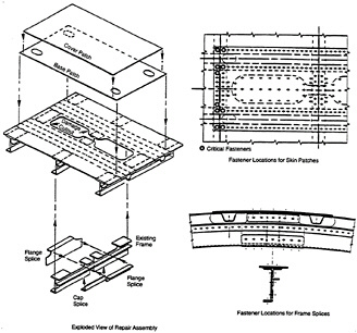
Figure 7-two Bolted splice repair of a composite primary structure panel. Source: Bodine et al. (1994).
undetectable defects or damage; establishing damage limits too equally specific inspection standards and techniques; and developing damage-tolerant, fatigue-resistant structural repairs for new materials along with the means for inspection validation.
The FAA should piece of work with the airline and manufacturing industries to develop mutual standards and procedures for maintenance and repair of aircraft construction. Application of new materials, processes, and component designs need to exist anticipated and accounted for in the FAA'southward research priorities.

Source: https://www.nap.edu/read/5070/chapter/9
Posted by: schradersammat.blogspot.com
0 Response to "How To Repair Fabric Aircraft"
Post a Comment